Designing the
![]() Airfoils
Airfoils
Through my association with the
CAFE Foundation, I have had the opportunity to be around a couple of world class airfoil designers, Ray
Hicks formerly of NASA and John Roncz.
 I found that there are a couple of schools of thought around designing
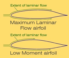
airfoils for this class of airplane. One "school" is to achieve maximum laminar flow for very low drag,
which usually produces an aft loaded airfoil with a fairly high pitching moment (the tendancy for the wing
to pitch nose-down). This is because the shape that allows for laminar flow is fairly critical and usually
doesn't produce much lift at the forward half of the wing, so there is a lot of lifting left to do on the
aft part of the wing. It then makes sense that by doing its lifting from the back, it would tend to force
the front downward.
I found that there are a couple of schools of thought around designing
airfoils for this class of airplane. One "school" is to achieve maximum laminar flow for very low drag,
which usually produces an aft loaded airfoil with a fairly high pitching moment (the tendancy for the wing
to pitch nose-down). This is because the shape that allows for laminar flow is fairly critical and usually
doesn't produce much lift at the forward half of the wing, so there is a lot of lifting left to do on the
aft part of the wing. It then makes sense that by doing its lifting from the back, it would tend to force
the front downward.
The other "school" is to make a low moment airfoil or even a positive moment and cleverly work the shape to get as much laminar flow as possible. This means creating a shape that produces more of the lift toward the front which usually decreases laminar flow on the upper surface (and leaves you with slightly more drag). The idea around the latter is that eliminating the nose down pitching tendency of the wing reduces the trim drag (the drag created by the horizontal tail to counter this nose-down tendency) and also increases stability for a given tail size.
My experience of both Ray Hicks and John Roncz is that they subscribe to the second school. Who am I to argue! I designed the airfoil for the HawkJET™ with this in mind.
Lets take a look to see some of
the reason Ray and John take this approach. To illustrate the affect of pitching moment, consider the
HawkJET™
with one of the newer NLF (Natural Laminar Flow) airfoils that has a moderate moment coefficient (Cm) of
-.10. Cruising at a speed of 350 knots, the
HawkJET™
wing would have a pitch-down torque of almost 6,000 foot-pounds! The horizontal stabilizer would have to
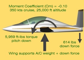 offset this nose-down tendency with a downward force of about 600 pounds. Since the wing ends up carrying
this load, it now has to support 21% more than the maximum gross weight of the entire airplane. This
increases the induced drag of the wing and tail (not to mention the awful mess the aft loaded airfoil makes
of the interference drag at the wing-fuselage junction). Just this added induced drag would cost six knots!
offset this nose-down tendency with a downward force of about 600 pounds. Since the wing ends up carrying
this load, it now has to support 21% more than the maximum gross weight of the entire airplane. This
increases the induced drag of the wing and tail (not to mention the awful mess the aft loaded airfoil makes
of the interference drag at the wing-fuselage junction). Just this added induced drag would cost six knots!
Now lets consider the airfoil designed specifically for the HawkJET™ with its essentially zero Cm. The drag of the wing itself is slightly higher because of the reduction in laminar flow (but only half of the trim drag of the NLF airfoil). There is no added induced drag because the tail doesnt need to push down with over 600 pounds of force. Plus the interference drag at the wing root is much easier to handle.
Now there are other NLF airfoils that don't have quite the negative pitching moment and have varying degrees of laminar flow, so they begin to approach the characteristics of the HawkJET™ airfoil. But NLF airfoils tend to exhibit their low drag ability only through a narrow window of their operating envelope. This means they are a drag advantage for only a small range of Angle Of Attack (AOA) and are a liability beyond that. So even when you are not operating at the optimum AOA you still have this large tail load to contend with. You then have to make the tail larger to handle this load which just adds more drag again. It sure seems that Ray and John have the right idea (and we haven't even discussed the structural ramifications of the extra tail load). It looks like a case of being penny wise and pound foolish.
Designing a wing with a custom airfoil can be risky. Just because the computer says it will fly, doesnt mean it will fly the way you want it to. Because of this I devised a method of tailoring the airfoil to the needs of the HawkJET™ that I consider relatively low risk. In past conversations with Ray Hicks, I learned that he sometimes creates an airfoil by combining the upper surface of one airfoil with the lower surface of another. When I asked if the new lower surface affected the pressure distribution over the upper surface, Ray said it does a little but not much.
One of the biggest concerns when designing a new airfoil is its maximum lift (Clmax) capability. This is also the most difficult aspect of the airfoil to predict with today's analytical methods. These predictions are basically unreliable so wind tunnel data is needed. The most critical portions of an airfoil that affect Clmax are the forward part of the upper surface and the leading edge radius. The HawkJET™ airfoils are basically NACA 6 series laminar airfoils mixing and matching upper and lower surfaces with a little scaling to adjust thickness. This gives an indirect correlation to known stall characteristics and Clmax with the wind tunnel test data for already existing airfoils. This is why I say it is relatively low risk. Even so, I am investigating ways to get real empirical data from these airfoils before the wing is built.
 The tools I use for airfoil
design are DreeseCode Softwares DesignFOIL and David Lednicers NACA Airfoil Generator. DesignFOIL and David
Lednicer's Airfoil Generator use the same built-in NACA formulas for creating airfoils and DesignFOIL also pedicts
pressure distribution and Drag Polars. David wrote the code in GW Basic which allowed me to easily modify it to
fit my specific needs. DesignFOIL is a great tool written by John Dreese who is a Wind Tunnel engineer and an
Aerodynamicist. David Lednicer is a CFD (Computational Fluid Dynamics) wizard, is active and well known in
aerodynamics circles and seems to know everything anyone needs to know about aerodynamics.
The tools I use for airfoil
design are DreeseCode Softwares DesignFOIL and David Lednicers NACA Airfoil Generator. DesignFOIL and David
Lednicer's Airfoil Generator use the same built-in NACA formulas for creating airfoils and DesignFOIL also pedicts
pressure distribution and Drag Polars. David wrote the code in GW Basic which allowed me to easily modify it to
fit my specific needs. DesignFOIL is a great tool written by John Dreese who is a Wind Tunnel engineer and an
Aerodynamicist. David Lednicer is a CFD (Computational Fluid Dynamics) wizard, is active and well known in
aerodynamics circles and seems to know everything anyone needs to know about aerodynamics.
Before designing the airfoils, I identified what I need them to do. In any design there is a dance, a balancing act, if you will, between all of the countering needs of the design. I want the wing to contain all the fuel so there needs to be sufficient volume. I want plenty of room for flaps and mechanisms so a razor thin trailing edge is out. I want near zero pitching moment so that says I want a forward loaded airfoil. Finally I want as low drag as possible, which means as much laminar flow as possible given these other parameters.
It is a balancing act because some of these needs are in direct conflict with others. Having sufficient volume for the required fuel dictates a fairly thick airfoil. This along with room in the trailing edge for the flap mechanism and the requirement of near zero pitching moment all fight against low drag.
The vast majority of laminar flow airfoils have the same amount of laminar flow on both the upper and lower surfaces. The pressure distribution around a wing creating lift is more favorable to sustaining laminar flow on the lower surface than the top. Taking advantage of this natural tendency (by creating more laminar flow on the lower surface) can make up for the laminar flow lost on the upper surface from designing the airfoil for low pitching moment. Plus, the shape created for the lower surface to obtain this added laminar flow will be favorable to the desired pitching moment.
Conventional wisdom also says that thick airfoils have lower maximum lift which would theoretically increase landing speed. However, thicker airfoils also have a higher increment of lift when using a flap. This means that what is lost in maximum lift without flaps, is regained when using flaps. With a fast, clean airplane like the HawkJET™, flaps are an integral part of drag management that enables the pilot to slow the airplane for landing. Thus, since flaps will always be used, there is no loss of maximum lift (Clmax) with the thick airfoil.
For the root airfoil, I came up with a section thickness that is 19 percent of the chord. It also has the trailing edge cusp removed (the concave portion of the teardrop at the trailing edge is now a straight line) for easier fabrication. The extent of laminar flow is over 45% on the upper surface, almost 70% on the lower surface and it has a slightly positive moment coefficient (most airfoils are negative which means they have a tendancy to want to pitch down). Interestingly, when comparing this airfoil with the highly touted, low drag airfoils of the P-51 Mustang, even though the HawkJET™ airfoil is much thicker (19% thick verses 15% thick) it has less drag. Also, the forward portion of the HawkJET™ airfoil is similar to the forward portion of the NACA 65-418 and since the Clmax for this airfoil is respectable, the HawkJET™ airfoil should be very similar.
 To get a sense of how these airfoils
perform, I create what I call a "Parametric Drag Polar". Whenever you see a drag polar, it is the drag vs.
lift at a given Reynolds Number. But for a given airplane, there is only one point on that entire drag polar
that applies. This is because the Reynolds Number of the polar applies to one specific velocity for the
airplane. It is this speed that defines the lift coefficient (given the weight of the airplane) that
correlates to the drag value in the afore mentioned drag polar.
To get a sense of how these airfoils
perform, I create what I call a "Parametric Drag Polar". Whenever you see a drag polar, it is the drag vs.
lift at a given Reynolds Number. But for a given airplane, there is only one point on that entire drag polar
that applies. This is because the Reynolds Number of the polar applies to one specific velocity for the
airplane. It is this speed that defines the lift coefficient (given the weight of the airplane) that
correlates to the drag value in the afore mentioned drag polar.
As an example, The HawkJET™ cruises at a lift coefficient of about 0.2 and a Reynolds Number of about seven million. However it stalls at a lift coefficient around 2.2 and a Reynolds Number about two million. The common approach with drag polars will have different graphs for each of those points. Why not have a single graph display all the lift/drag data at the appropriate Reynolds Number? This is exactly what the Parametric Drag Polar is! The information is much more representative of what is really going on and this makes the drag polar a lot more useful.
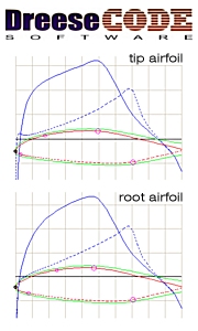
The Parametric Polars shown here are for the wing root and the wing tip. Since the chord of the root and tip are different, the Reynolds Numbers are also different. These graphs have taken that into account. You can see, even with the different needs of the airfoils at the root and tip, the lift/drag characteristics are remarkably similar. They have laminar flow over almost 60% of their surface so the drag is quite low. Plus they have very wide drag buckets, making this low drag available through a wide range of the performance envelope.
Since the HawkJET™ is designed to cruise at 350 knots at 25,000 feet altitude it will be operating at Mach .58 (58% of the speed of sound). At this mach number and using a thick airfoil, compressibility (local velocities over the airfoil reaching the speed of sound) can become a factor. Using DesignFOIL to show the maximum velocity for both HawkJET™ airfoils shows the maximum local velocities of either airfoil to be around Mach .77. This leaves plenty of margin so there is no concern about compressibility.
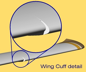
 The wing tip airfoil is the same as
the root with the addition of the cuff section to droop the leading edge and increase the chord. Years ago
I had lengthy conversations at Oshkosh with Jim Griswold and Doug Griswold about the design of the cuff
on the Questair Venture. The cuff alters the airfoil to increase the chord by 3% and lower the angle of
attack by one half of a degree. To accomplish this I simply scaled sections of some existing airfoil curves
with the desired shape, beginning at the highest point on the upper surface and the lowest point on the
lower surface. After modifying the shape,
The wing tip airfoil is the same as
the root with the addition of the cuff section to droop the leading edge and increase the chord. Years ago
I had lengthy conversations at Oshkosh with Jim Griswold and Doug Griswold about the design of the cuff
on the Questair Venture. The cuff alters the airfoil to increase the chord by 3% and lower the angle of
attack by one half of a degree. To accomplish this I simply scaled sections of some existing airfoil curves
with the desired shape, beginning at the highest point on the upper surface and the lowest point on the
lower surface. After modifying the shape,
 I used a CAD (Computer Aided Design) program to display the airfoil's curvature along its length to make
sure it wasn't "lumpy". I then used DesignFOIL to make sure the modification didnt create any significant
discontinuities in the pressure distribution and to confirm it had the desired characteristics. DesignFOIL
also showed a lift coefficient slightly less than the root airfoil at the angle of attack they both will
operate on the completed wing. This will give a slight effect of washout (twist) to the wing, which should
favorably effect the stall characteristics along with the effect of the cuff itself.
I used a CAD (Computer Aided Design) program to display the airfoil's curvature along its length to make
sure it wasn't "lumpy". I then used DesignFOIL to make sure the modification didnt create any significant
discontinuities in the pressure distribution and to confirm it had the desired characteristics. DesignFOIL
also showed a lift coefficient slightly less than the root airfoil at the angle of attack they both will
operate on the completed wing. This will give a slight effect of washout (twist) to the wing, which should
favorably effect the stall characteristics along with the effect of the cuff itself.
Analyzing both airfoils with DesignFOIL reveals, [1] very good overall drag when compared to other popular NACA airfoils (much lower drag than the Questair Venture airfoils), [2] very low (or positive) moment coefficients and [3] they are relatively thick airfoils and provide sufficient volume in the wing for fuel and various mechanisms. Plus this thickness allows for more spar depth which makes the structure lighter.
![]()
![]()
![]()
![]()